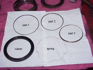
| In fig. 2 all five parts are arrayed. At lower left is the rubber
part. Then clockwise are three steel rings I've numbered part 1, part 2, and part 3. The
following photos show these parts separately, some with some closeups. At the lower right
is the spring. The metal parts 1 and 2 fit together with the spring to make the framework shown in fig. 7. The framework is installed on the inside of the rubber part. Then part 3 presses in from the outside capturing the rubber between its inside diameter and the inside diameter of part 2, so locking the framework to the rubber. This is shown from the inside in fig. 11 and from the outside in fig. 12. Fig.12 shows the inner surface of the rubber with the framework removed. Fig.13 shows the lip on the outside of the rubber which can be seen in the cross-section drawing. |
|
|
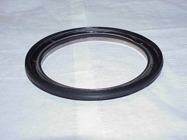
| Fig.1 : Complete seal seen from the inside (of the bearing) | Pig.2 : All the parts that form the seal |
 |
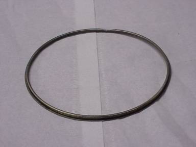 |
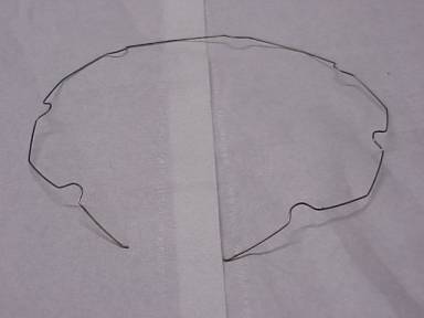
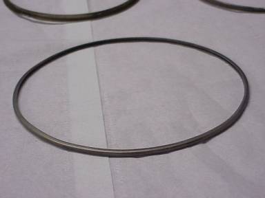
| Fig.3 : Spring | Fig.4 : Part 1 |
 |
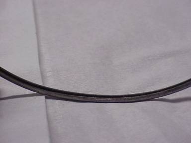 |
| Fig.5 : Part 2 | Fig.6 : Close up of part 2 |
| The metal parts 1 and 2 fit together with the spring to make the framework shown in fig. 6. |
 |
|
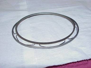
| Fig.7 : Framework (metal parts 1 and 2 + spring) |
 |
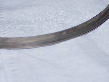 |
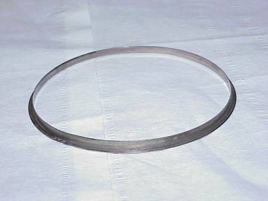
| Fig.8 : Part 3 | Fig. 9 : Close up of part 3 |
| Then part 3 presses in from the outside capturing the rubber between its inside diameter and the inside diameter of part 2, so locking the framework to the rubber. This is shown from the inside in fig. 10 and from the outside in fig. 11. |
|
 |
| Fig.10 : Complete seal (inside view) | Fig.11 : Complete seal (outside view) |
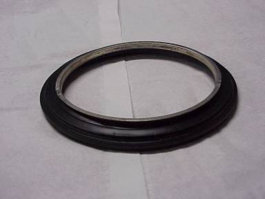
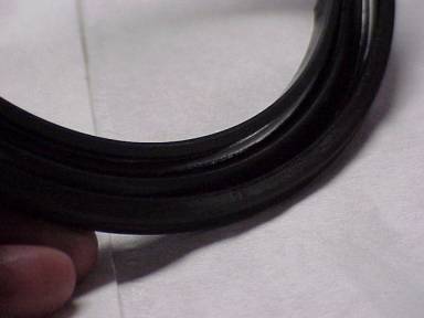
| Fig. 12 shows the inner surface of the rubber with the framework removed. Fig. 13 shows the lip on the outside of the rubber which can be seen in the cross-section drawing. |
 |
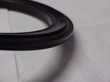 |
| Fig.12 : Inner surface of rubber | Fig.13 :Lip on outside of the rubber |
| All pictures by Carter Willey, text by Carter Willey |