Distribution and regulation of pressure

| Pressure distributor | Pressure control-valve |


This chapter is independant of the hydraulic system or units of the " D " models. The pressure distributors and regulators are integral parts of many of the hydraulic units. It is therefore essential to know their principles of operation to understand the working of the units.

I - PRESSURE DISTRIBUTOR

A pressure distributor is a tap which will admit or exhaust fluid under pressure to or from one or more circuits.

A distributor may also isolate this unit or units from both the " inlet " and the " exhaust " lines.

The Pressure Distributor is generally a slide-valve operating in a sleeve. Only the position of the slide-valve is the controlling factor of the operation of the circuits.

An example of this type of distributor, as used on the " D " model, is the gear selector slide-valve.

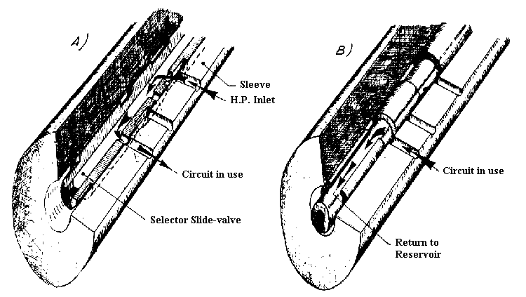
The gear-selector slide-valve is hollow, and has 1 inlet for the supply of the fluid at High Pressure and 5 outlets (1 for each gear) to supply the gears.

Longitudinal and circumferential grooves machined in the slide-valve allow the fluid to return to the reservoir from the various circuits. The sleeve has 5 ports, one to supply each gear.

  • With the valve at rest (Neutral), the various outlets from the slide-valve align with a plain part of the sleeve. The various ports of the sleeve communicate with the reservoir via the grooves in the slide-valve.
  • Pressurisation (Diagram A) : When the slide-valve is moved, a port is aligned in the latter with a corresponding port in the sleeve and the circuit is pressurised.
  • De-Pressurisation (Diagram B) : With the slide-valve in any position which allows alignment of an outlet to a circuit to communicate with the return to the reservoir, the fluid under pressure in that circuit will flow out and return to the reservoir.

NOTE : The operation of this distributor is independant of the amount of effort applied 10 the slide-valve when it is being moved. Only the movements and positioning of the latter permit the distribution of fluid.

A further type of pressure distributor : The height correctors, the operation of which we saw in chapter 4.

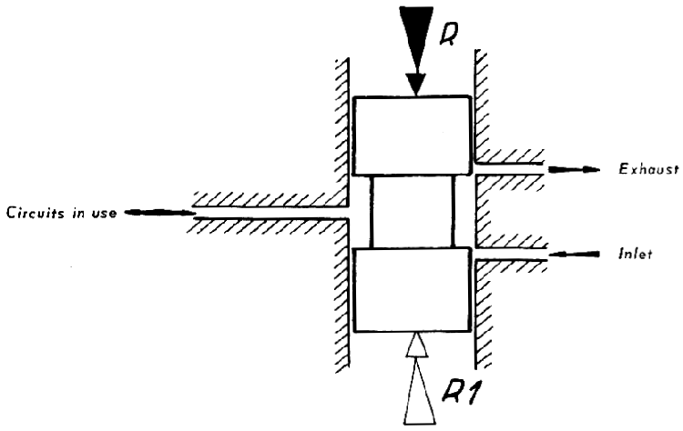
A slide-valve- with two shoulders slides in a sleeve in which there are three ports.

  • In the neutral " position the slide-valve closes the " inlet " and " exhaust " ports. The supply port to the circuit is always open.
  • Pressuration : For the slightest effort "R" on the slide-valve, it will move so that the "inlet" port is opened. The circuit is then connected to the source of pressure. Thus the pressure in the source of pressure circuit will enter the circuit in use and the pressure values in two circuits will be equal regardless of the effort on the slide-valve.
  • De-pressurisation : On the other hand a force R. 1 (opposed to K) applied to the slide-valve will move it so that the "exhaust" port is opened. The fluid under pressure in the circuit in use will flow out and return to the reservoir.

    NOTE : The forces R and R. 1 are connected with the operation of the slide-valve only by the presence of a dash-pot in the height corrector.

    Sometimes hydraulic units can only be made to operate correctly by using a pressure lower than that in the Source of Pressure circuit. In some cases it is necessary to use :
      - A variable but controllable pressure (steering, braking, etc.)
      - A constant but relatively low pressure (clutch).
    A simple pressure distributor cannot fulfil these conditions.
    A pressure control-valve makes it possible to supply these different units correctly.


II - PRESSURE CONTROL-VALVE

1)

Description :
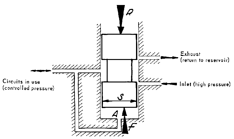
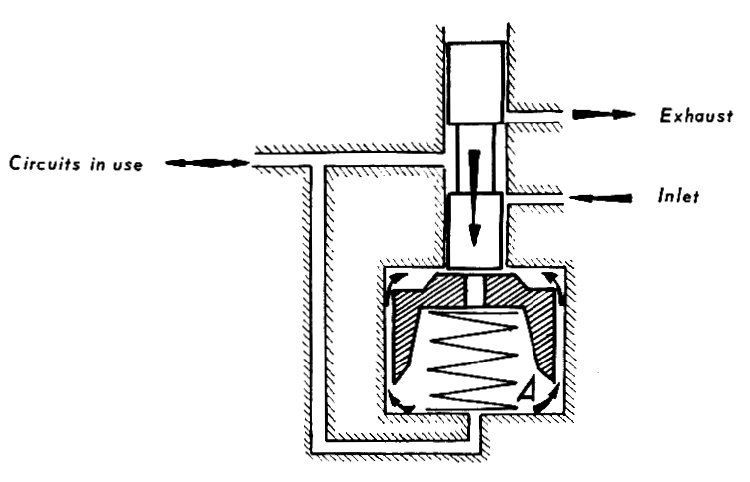
The diagram below shows the various parts which comprise the pressure control-valve.
The force R applied to the end of the slide-valve may be the strength of a spring, the effect of the different calibrations of several springs, or a physical effort.

2)

Operation :
a) Pressuration :

To make the control-valve operate it is necessary to connect the source of pressure with the circuits to be used.
This operation may be :
- Automatic
: at rest the source of pressure is connected to the circuit.
- Controlled manually : at rest the position of the slide-valve is not important. 
When pressure rises in the circuit in use : this very pressure P rises also in the chamber A under the slide-valve. 
A force F = P x S opposes the force R (S = The surface area of the slide-valve).

b) Equilibrium :

When F becomes equal to R the slide-valve takes up a position of equilibrium in which both the "Inlet" and "Exhaust" ports are closed. 
The pressure in the circuit is therefore limited to a value 

P = R / S

This pressure is independant of that existing in the source of pressure circuit. If the force R is increased, the controlled pressure rises, and vice versa.

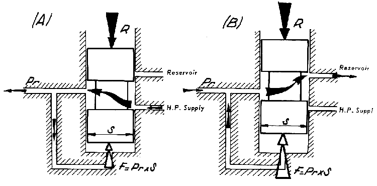
For a fixed value of R :

  • If the pressure drops in the circuit being used, F decreases, R prevails, the slide-valve moves to the "Inlet" position, and the regulated pressure Pr increases (Figure A).
  • If the pressure rises in the circuit being used, F increases, the slide-valve moves to the "Exhaust" position and the pressure decreases (Figure 8).
  • These two possibilites, resulting from seepage and friction between the slide-valve and its sleeve, result in the regulated pressure oscillating between two values very near the theoretical pressure.

c) Applications :

  • If R is the calibrated strength of a spring T, a regulated pressure is obtained :
                                                                     Pr = T / S
    Example : Automatic gearchange slide-valve in the gear selector.

  • If R is a variable manual force, or the variable calibration of a spring (the calibration varying with the movement of the spring's abutment) a pressure is obtained which is pro-portional to the force R.
    This is therefore an "adjustable" regulator.
    Example : Hydraulic brake control, Centrifugal Regulator.

b) Dash-Pots :

To avoid a rise of pressure which is too rapid in the circuit in use the movement of the slide-valve may be slowed down by the use of a dash-pot. This method also avoids oscillation of the slide-valve.

A piston with a calibrated amount of clearance slides in the chamber A, the diameter o which is greater than the slide-valve.

When the slide-valve moves down, the fluid is restricted in its movement between the piston and the walls of the chamber A, which slows down the movement of the valve.

A weak spring and a hole drilled in the head of the piston allow a rapid return of the slide-valve.

Back to top of page