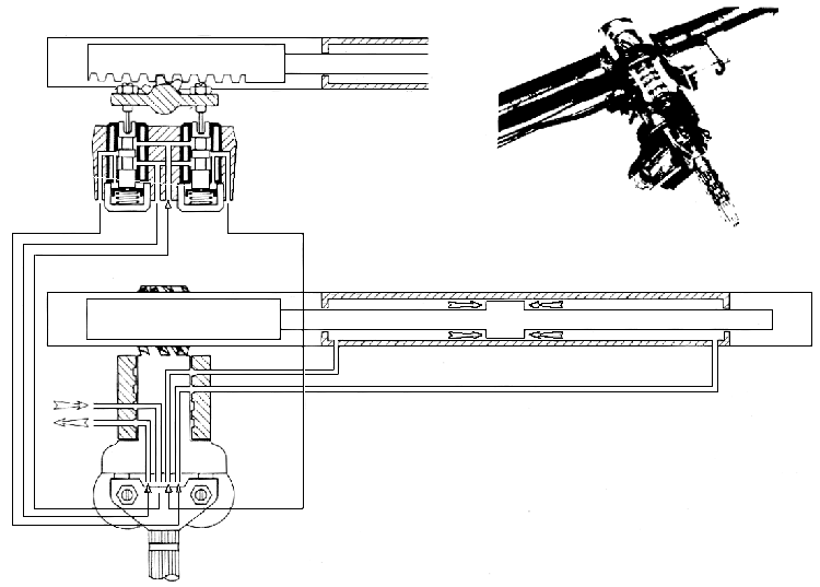
| 1) |
No movement of the steering wheel :
The fork is at rest and the pressure-control slide-valves are also in
equilibrium, closing the inlet ports in the valve block.
|
| 2) |
Movement of the Steering Wheel :
When the wheel is turned, this leads to a movement of the slide-valves
in relation to their sleeves in the valve block. One slide-valve moves
down, the other rises.
The valve which moves down connects high-pressure to one side of the
piston.
The second slide-valve which rises, allows the fluid on the other side
of the piston to return to the reservoir.
|
| 3) |
Stopping of the Steering Wheel :
When the rack moves it turns the pinion, which moves the sleeves, in
which the control slide-valves are situated, in the direction which would
tend to make the valves return to the cut off position.
As long as the driver turns the steering wheel he holds the
slide-valves in the open position, but when he ceases to turn, the sleeves
return to their cut off position in relation to the slide-valves and the
rack stops moving.
|
| 4) |
Residual Pressure :
A residual pressure is maintained on either side of the piston when the
steering is at rest. This pressure is maintained by the
pressure-distributor valve assembly and its value is a function of the
position of the pressure-control slide-valves in their sleeves. (The
Crossover pressures).
- Because of this, any movement of the steering wheel causes an
immediate response of the rack, by virtue of rising pressure on one
side of the piston and falling pressure on the other side. The
movement of the rack is thus immediate.
NOTE : A dash-pot is situated under each slide-valve.
|
| 5) |
Mechanical Linkage :
- Steering without Pressure : To provide a mechanical linkage,
the fork has two pegs which operate the pinion direct. These pegs have
some play in their housing ; this play allows :
- under pressure, the movement of the pinion before the slide-valve.
- without pressure, movement of the pinion before the slide-valves
reach the end of their travel in the sleeves.
- Steering Under Pressure : The play is not felt : the residual
pressure which acts equally on both slide-valves keeps them in contact
with the fork.
|