Hydraulic control of clutch and gearchange

| General Details | Circuit Layout | Hydraulic Gear Selector | The Centrifugal Regulator | Clutch Lock | Clutch Reengagement Control | Gearchange Speed Regulation |


I - GENERAL DETAILS

  • To carry out all the operations relative to changing gear and using the clutch, the driver uses only the gear lever and the accelerator pedal. The vehicle has a conventional gearbox and clutch, the clutch and gearchange operations are carried out automatically.
  • This automatic control is maintained by two principal units : 
    - the hydraulic gear selector.
    - the centrifugal regulator.

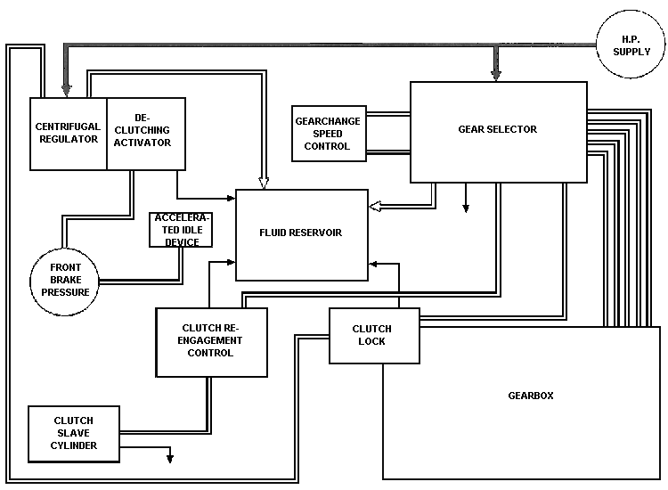
II - CIRCUIT LAYOUT


III - HYDRAULIC GEAR SELECTOR

1)

Purpose :

  • The hydraulic gear selector ensures de-clutching in neutral, and from neutral allows the engagement of any gear.
  • During the gearchange cycle, it controls in the following order :
    • de-clutching,
    • dis-engagement of the gear in mesh,
    • engagement: of the gear selected,
    • re-engagement of the clutch.
2) Description :
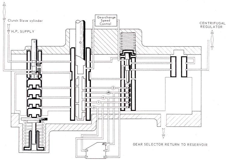
The various elements of the hydraulic gear selector are :
a)

the selector slide-valve :

  • This is hollow and has 1 inlet port for HP fluid and 5 outlet ports (one for each gear).
  • Longitudinal and circumferential grooves are machined in the slide-valve to allow the return of fluid to the reservoir by way of the front face of the gear selector. (From a gear, for example).
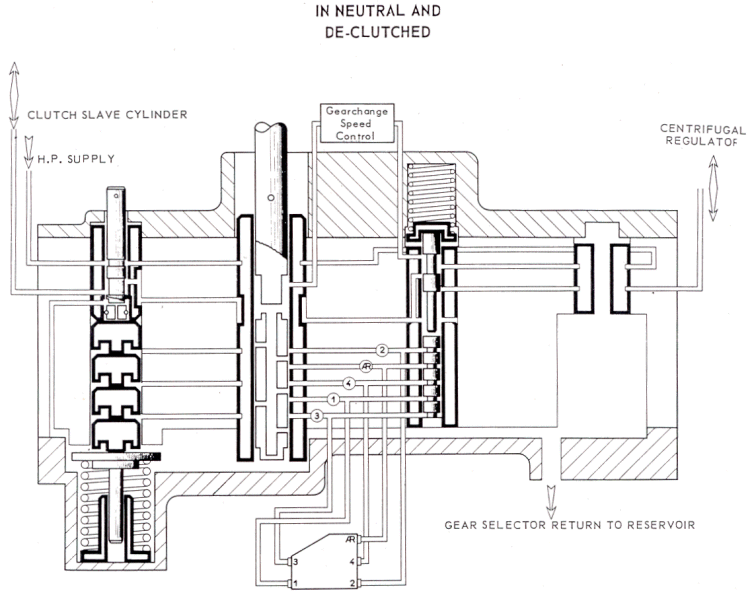
  • In neutral the outlet ports in the slide-valve are opposite a plain part of the sleeve in which it operates. Sealing is maintained only by the accuracy of the machining of the slide-valve and its sleeve. (A tolerance of a few microns).
  • The positioning of the slide-valve in its sleeve is very important, and is the object of a very precise setting which corresponds to a given position of the gear lever.
b)

The automatic clutch control pistons :

  • Five in number (1 for each gear), are able to move upwards in the gear selector when they are pressurised. They return to their initial position by means of the return spring of the automatic clutch control slide-valve.

c)

The automatic clutch control slide-valve.

d)

The synchro-delay pistons :

  • Four in number, only three of which can move, the fourth being a plug. They are returned to their initial position by two return springs.
  • There is no synchro-delay piston for 1st gear, although it is synchronised.

e)

The manual clutch control slide-valve :

Controlled manually by a lever and a rod, and has only two positions.

  • normal driving position. (Slide-valve in).
  • de-clutched position. (Slide-valve out).

At its lower end are two drillings at right-angles to each other. (As shown in diagram).

f)

Internal passages :

The five outlets to the gearbox pistons, shown on the diagram by numbered rings, are connected to the automatic clutch control pistons.

3)

Operation :
a) Manual clutch control :
  • The slide-valve in its normal position : fluid under high pressure is supplied to the hydraulic gear selector.
  • The slide-valve in its withdrawn position : in this position the slide-valve.
    • cuts off the supply of HP fluid to the clutch and gearchange circuit :
    • allows the fluid in the clutch slave cylinder to escape to the reservoir.
  • In the latter position of the slide-valve, the vehicles clutch is engaged, which allows :
    • the freeing-off of the motor and starting on the handle.
    • valve clearance adjustments, etc . . .
b) Rise of pressure - de-clutching : (manual clutch control slide-valve in its normal position)
  • Before the hydraulic selector slide-valve is supplied with fluid under pressure, the position of the automatic clutch control slide-valve is such that :
    • the supply to the selector slide-valve is cut off.
    • the port to the clutch slave cylinder is open.
  • When HP arrives the slide-valve operates as a pressure control valve and de-clutching occurs at a pressure of 50-70 bars ( 725 to 1000 psi). (This pressure is the result of the calibration of the spring above the slide-valve).
  •  In its regulating position the slide-valve allows fluid to pass to the selector slide-valve, (via the gearchange speed control).
  •  Therefore, with the engine idling, in neutral,-the clutch is out.

c)

Engagement of 1st or reverse gear :

By moving the lever the selector slide-valve Is aligned in such a way that the line to che chosen gear is pressurised. The pressure rises simultaneously :

  • in the gear circuit, (gear selector fork shaft pistons).
  • in the automatic clutch control pistons.

The surface area of the pistons and the strength of the springs are such that che pressure causes :

  • Immediate movement of the gear selector fork shaft until the gear is engaged.
  • Then, as the pressure continues to rise, the movement of che automatic clutch control piston..

d)

Engagement of 2nd, 3rd, or 4th gears :

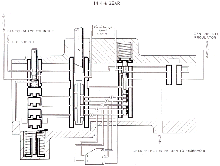
When the chosen gear circuit is connected to the supply of pressure (by the selector slide-valve) the pressure rises simultaneously :

  • in the gear circuit (gear selector fork shaft pistons).
  • in the automatic clutch control piston circuit.
  • in the synchro-delay piston circuit.

For the aforementioned reasons, the different phases of operation occur in the following order :

  • Movement of the selector fork shaft until synchro cones begin to contact.
  • Movement of the synchro delay piston : which allows the volume of fluid to increase and the pressure to stabilise (while synchronisation continues at a constant pressure).
  • Rapid movement of the selector fork shaft allowing full engagement of the gear once the synchro piston has bottomed.
  • Movement of the appropriate automatic clutch control piston.

e)

Re-engagement of the clutch :
  • Whatever gear is selected, the final operation of the gear selector is the movement of the automatic clutch control piston.
  • As it moves, the piston causes the automatic clutch control slide-valve to rise. The equilibrium of the pressure balance is upset, and in its new position the slide-valve allows :
    • Fluid to pass to the selector slide-valve (This pressure holds the gear in engagement).
    • The connection of the clutch slave cylinder to the centrifugal regulator, (We shall see that clutch dis-engagement and re-engagement can take place when the centrifugal regulator allows the fluid in the slave cylinder to escape back to the reservoir).

f)

Return to neutral :

Between each gear the selector slide valve connects all the circuits under pressure to return to reservoir via the grooves it carries. All the parts return to their initial positions under the action of their return springs.


IV - THE CENTRIFUGAL REGULATOR

1) Purpose :

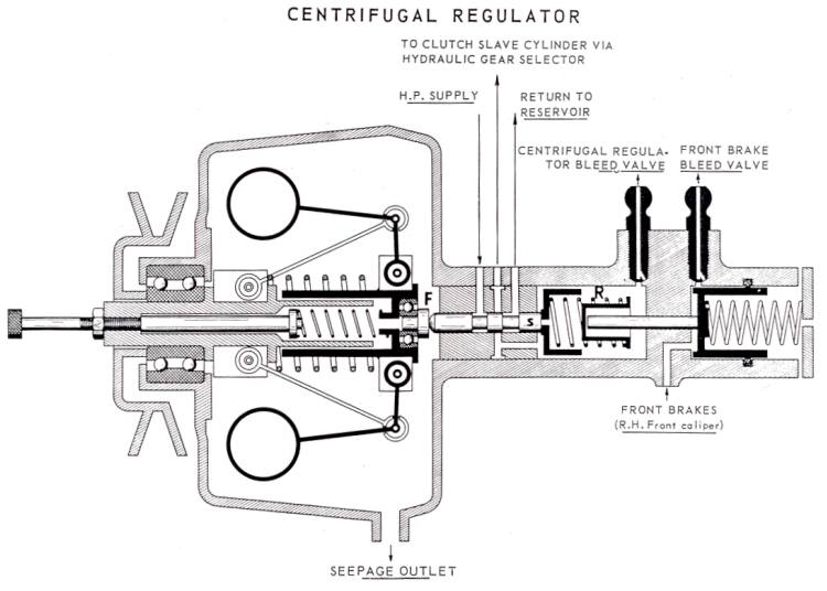
The centrifugal regulator controls the clutch engagement when moving off and its dis-engagement when the vehicle stops with a gear still engaged. Its operation is in relation to engine speed.

2) Description :

It comprises three major parts :

  • A classic type centrifugal governor
  • A pressure control slide-valve and sleeve assembly
  • a de-clutching activator fed by pressure from the front brakes.
3) Operation :
a) Centrifugal governor :
  • This transmits by way of a pressure pad, to the control slide-valve, a force which varies with engine speed :
    • With the engine stopped, this force corresponds to the calibration of the springs.
    • When turned the weights fly outwards, compressing the springs until there is a state of balance between the centrifugal force and the spring pressure.
  • The force F transmitted to the slide-valve by the pressure pad becomes progressively less as the engine speed rises.
b) Pressure-control slide-valve assembly :
  • The slide-valve and its sleeve act ag a pressure-control device
    • Equilibrium of the slide-valve is achieved when the forces acting on its end (pressure and spring) are equal to the force exerted by the pressure pad.
                                        p x s + R = F

    • The operating pressure (regulated pressure) is thus solely a function of the force F, namely the engine speed.

                                        p = (F-R) / s
  • Thus the regulated pressure diminishes when the engine speed is increased and vice-versa.

NOTE : When the clutch is engaged, the slide-valve's position connects the clutch circuit to the return system.
Therefore, during gearchanges, only the automatic clutch control slide-valve controls de-clutching and engagement.

  • A dash-pot is provided to damp sudden pressure rises and the movement of the control slide-valve.

c)

De-clutching activator :

Purpose : 

  • The activator facilities the dis-engagement of the engine from die gearbox during a rapid stop with the brakes applied and a gear engaged. Complete de-clutching is obtained by increasing the pressure in the clutch circuit by about 10 bars (145 psi).
Operation :
  • When decelerating, [he pressure in the brakes also acts on the de-clutching activator piston, compressing its return spring.
  • As it is moved back, the piston effectively reduces the strength of the spring R at the end of the slide-valve.
  • For a given engine speed, the slide-valve's equilibrium is obtained with a higher pressure

                                      previously p = (F - R) / s
  • R becomes less, F remains constant, so p increases (by 10 bars, approx 145 psi).

d)

Adjustment of the clutch engagement speed :

Let p be the pressure corresponding to clutch drag at a given engine speed.

  • By screwing in the adjuster screw, F increases, p increases. The pressure corresponding to the clutch drag will be obtained ar higher engine revolutions.
  • By unscrewing : the reverse occurs.

V - CLUTCH LOCK

1) Purpose :

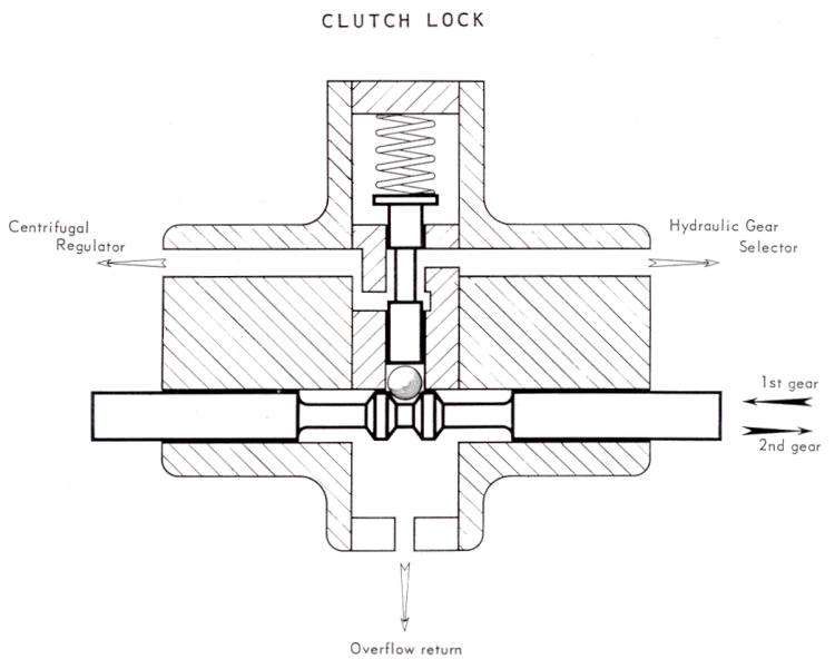
This unit is present to stop the clutch fe-engaging during changes to and from 1st and 2nd gears, if one or other of the gears is not fully engaged. This safety measure is mainly justified on the re-engagement in 1st gear ; due to the absence of a 1st gear synchro delay piston in the hydraulic selector, the latter could allow re-engagement before the synchro and locking dogs have had time to operate.

2) Description :

The clutch lock is fitted to the right hand front side of the gearbox, in the hydraulic circuit between the gear selector and the centrifugal regulator.
Thus it cannot hinder de-clutching during gearchanges even if it is closed.

It comprises :

  • 1 body
  • 1 slide-valve sleeve
  • 1 slide-valve with a central groove
  • 1 return spring for the slide-valve
  • 1 ball control rod and ball

This ball control rod is connected to the selector fork shaft for 1st and 2nd gears by a lever and spring.

3) Principle :

The principle is to block the pressure-release circuits if either 1st or 2nd gears are not fully engaged; or neutral.

4)

Operation :

When 1st or 2nd gears are being engaged, the ball, lifted by a shoulder on the ball control rod, pushes the slide-valve which blocks the fluid passage. As long as synchronisation and engagement do not take place the selector fork shaft (1st and 2nd) and the ball control rod remain in this intermediate position, and stop the escape of fluid from clutch slave cylinder.

When the locking dogs are fully engaged the selector fork shaft and the ball control rod move again and the shoulder no longer holds up the ball which returns down with slide-valve under the influence of the return spring.

Fluid may now pass the groove in the slide-valve and clutch re-engagement takes place.

For the engagement of 3rd or 4th gears the selector fork shaft for 1st and 2nd remains in neutral and the clutch lock stays open all the time.


VI - CLUTCH REENGAGEMENT CONTROL

1) Purpose :
This unit is present to ensure rapid and progressive re-engagement. 
It must :
  • Vary the speed of clutch re-engagement according to the position of the throttle
  • Allow rapid dis-engagement of the clutch
2) Description :
In the hydraulic circuit the CRC is situated between the gear selector and the clutch slave cylinder.

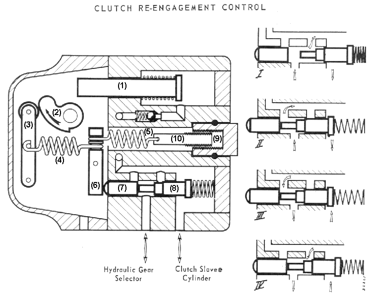
A cam, connected to the primary throttle butterfly spindle by a "Flector" acts, via a roller, on a lever which tensions a spring which in turn permanently applies pressure to a slide valve.

Another "By pass" slide-valve is pushed towards the first by a week spring. In the centre of this slide-valve the diameter is smaller than the bore in which it operates.

3) Principle and Operation :
a) Declutching :

Principle :
It is necessary for this operation to be as quick as possible. Therefore the CRC must not obstruct the flow of fluid from the gear selector to the clutch slave cylinder at all.

Operation :
Let us start from the position where the clutch is fully engaged. Pressure from the gear selector when de-clutching first moves the by-pass slide-valve back because its return spring is weak. The by-pass valve opens a port which allows free passage to the fluid going towards the clutch slave-cylinder. (Inset I),

As the pressure rises, the second slide-valve is moved in turn opening a second port and stretching the spring in the CRC. The movement of this slide-valve stops when its return lever bottoms, when the pressure reaches its maximum it becomes equal on both sides of the by-pass valve which returns to its original-position under the influence of its spring. (Inset II).

De-clutching is rapid as the fluid is virtually unobstructed.

b) Re-engagement :

Principle :
It is necessary to have a rapid first stage of engagement to the point where t;he clutch begins to drag and a slower second stage to avoid sudden engagement. To achieve this the return of fluid must be free at first and slowed down thereafter.

Operation :
The pipe connected to the hydraulic gear selector is connected to the return to the reservoir by the gear selector.

There is a rapid drop of pressure (Inset III), until the slide-valve obstructs the return port ; this occurs when the fluid pressure on one side of the slide-valve becomes less than the effect of the spring on the return lever on the other side.

This is the first phase, or rapid phase of re-engagement. In the centre portion of the bypass valve is the reduced diameter described in the text, this is between the outlet port and the return to gear selector ; the pressure continues to drop by way of the outlet, restricted by the bypass valve, but slowly now.
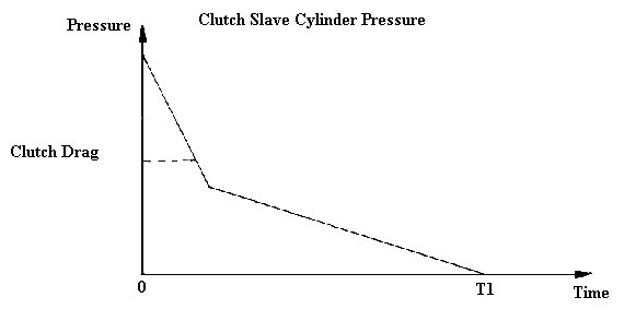
However it is necessary to vary the speed of clutch engagement according to the driver's wishes. To achieve this the phase-change pressure is altered. By reducing this pressure the rapid-drop phase is lengthened which results in the overall time of engagement being reduced.

The limits of this variation are : clutch slip in one sense and jerky engagement in the other.

When driving, this variation is obtained by the rotation of the cam which alters the spring tension in the CRC.

Eg : Under acceleration the pressure on the slide-valve decreases so the overall time of re-engagement decreases, (T2).
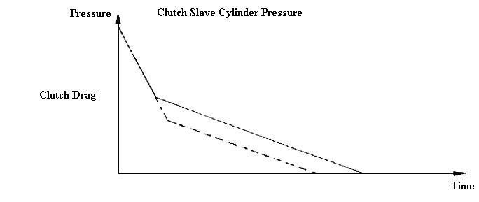
There is a fine static adjustment of the spring in the CRC by means of a second spring, the tension of which is variable by a screw and nut system. (By tightening the time of re-engagement is reduced).

Throttle closing Piston :
So that the engine speed is not excessive at the point of clutch re-engagement, it is limited during declutching. Mainly this permits the driver to keep the acceleration applied when changing down without affecting the smoothness of clutch engagement.

While the pressure is rising in the slave cylinder, the fluid pushes on the throttle-closing piston. The entry of fluid to the piston is slowed by making it pass a ball with 3 grooves on its seating, the fluid passing by the grooves. The restriction of the fluid is necessary to avoid "hammering" in the hydraulic circuit, and above all to prevent the throttle from being closed too quickly.

The piston moves out and limits the movement of the cam connected to the throttle spindle. The engine speed is limited while the clutch is out. Upon re-engagement, the pressure drops at the same speed as in the clutch slave cylinder, and the piston returns under the influence of its return spring.


VII - GEARCHANGE SPEED REGULATION

1) Purpose :
The hydraulic fluid which operates the gear-change circuits is not always at the same temperature or pressure when it reaches the hydraulic gear selector. If not corrected, these variations would cause errors in the times for gear operation. To overcome this, the fluid operating the gears passes through a gear change speed regulator mounted on top of the hydraulic gear selector.
2) Description :
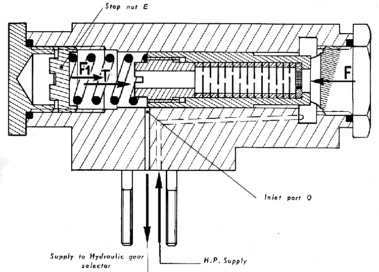
The regulator consists of a cylinder closed at each end by a plug, and in which a hollow piston slides.
Some washers, each with a small hole, some central, some offset, held apart by hollow spacers, form a zig-zag restricted fluid passage and are the internal parts of the piston. A carefully calibrated spring positions this piston.
3) Principle and Operation :
Upon entering the regulator the fluid under pressure creates a force F which tends to move the hollow piston across so that its end partially closes the outlet 0.
  • The return spring experts a force T on the piston in opposition to F.
  • The fluid under pressure passes through the filter and the various washers to supply the gear circuits.
  • The piston is acted upon from one side by the force F from the fluid, and from the other by the force T from the spring to which is added therefore F1 from the backpressure in the circuits in the gear selector.
    Depending the values of F and F1, the position of the piston varies, covering the outlet port.O to a greater or lesser extent. By the regulation of this outlet, the pressure is regulated.
    • The force F1 is variable, its value depends upon the resistance to flow through the gear selector. If this resistance is high the difference between F and F1 decreases and the piston opens the port more : the pressure remains constant. 
      Conversely if this resistance is low F1 decreases and the piston obscures more of the port, the pressure stays the same.
    • The force F is variable and depends on the source of pressure, and depending on this value, the outlet port O will be more or less obstructed.
  • It should be noted that the flow of fluid through the hollow piston is such that it is not affected by the viscosity or temperature of the fluid.

NOTE : The position of the nut E, used to set the value of force T of the spring, must never be altered.


Back to top of page